
精通
英语
和
开源
,
擅长
开发
与
培训
,
胸怀四海
第一信赖
精通
英语
和
开源
,
擅长
开发
与
培训
,
胸怀四海
第一信赖
锐英源精品开源心得,转载请注明:“锐英源www.wisestudy.cn,孙老师作品,电话13803810136。需要全文内容也请联系孙老师。
OCR是指光学字符识别,经常用于图像设备行业、办公行业、监控行业和安全行业等。在国内,大公司推出有收费的服务,对中文支持的比较好。普通的开源项目对中文支持的不太好。OCR对技术要求高,汉字识别率是一个重要的参数。本文对一些常用的技术进行了翻译。
The OCR (Optical Character Recognition) algorithm relies on a set of learned characters. It compares the characters in the scanned image file to the characters in this learned set. Generating the learned set is quite simple. Learned set requires an image file with the desired characters in the desired font be created, and a text file representing the characters in this image file.
In the below discussion the learned set is in xml format. This learned set is basically coordinates related information which will be explained in below article.
The below article describes the OCR recognition character example. Generating the learned set for different font style and sizes will be described in my next article. In this article we have already generated learned character set for font style verdana and font size 8px.
OCR(光学字符识别)算法依赖于一组学习字符。它将扫描图像文件中的字符与此学习集中的字符进行比较。生成学习集非常简单。学习集需要创建具有所需字体的所需字符的图像
文件,以及表示该图像文件中的字符的文本文件。
在下面的讨论中,学习集是xml格式。该学习集基本上是坐标相关信息,将在下面的文章中解释。
下面的文章描述了OCR识别字符示例。我将在下一篇文章中介绍为不同的字体样式和大小生成学习集。在本文中,我们已经为字体样式verdana和字体大小8px生成了学习字符集。
Four basic algorithms
• Image labelling.
• Finding boundary and Generating X, Y coordinate pixel array.
• Matching connected pixels with learned set (.xml).
• Forming words.
四种基本算法
•图像标注。
•查找边界和生成X,Y坐标像素阵列。
•将连接的像素与学习集(.xml)匹配。
•形成单词。
Image labeling algorithm:
It uses the Two-pass algorithm, which relatively simple to implement and understand, the two-pass algorithm iterates through 2-dimensional, binary data.
The algorithm makes two passes over the image: one pass to record equivalences and assign temporary labels and the second to replace each temporary label by the label of its equivalence class. 图像标注算法:
采用两遍算法,实现和理解相对简单,两遍算法迭代二维二进制数据。该算法对图像进行两次传递:一次传递等价记录并分配临时标签,第二次用每个临时标签替换其等价类的标签。
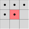
Connectivity checks are carried out by checking the labels of pixels that are North-East, North, North-West and West of the current pixel (assuming 8-connectivity). 4-connectivity uses only North and West neighbors of the current pixel. The following conditions are checked to determine the value of the label to be assigned to
the current. 通过检查当前像素的东北、北、西北和西的像素标签来执行连通性检查(假设为8连接)。4连接仅使用当前像素的北和西相邻点。
检查以下条件以确定要分配给当前的标签的值
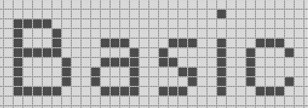
The above enlarged image is a pixel representation which serves purpose for our discussion. Every pixel in the bitmap image is represented
by its X and Y coordinates. The letter "B" in the above example shows how all the pixels are connected.
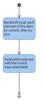
The image labeling algorithm will label the entire connected pixel with the same label. The UML diagram below illustrates the flow of the algorithm.上面的放大图像是像素表示,其用于我们的讨论目的。位图图像中的每个像素由其X和Y坐标表示。
上例中的字母“B”表示所有像素的连接方式。图像标记算法将使用相同的标签标记整个连接的像素。下面的UML图说明了算法的流程。
On the first pass:
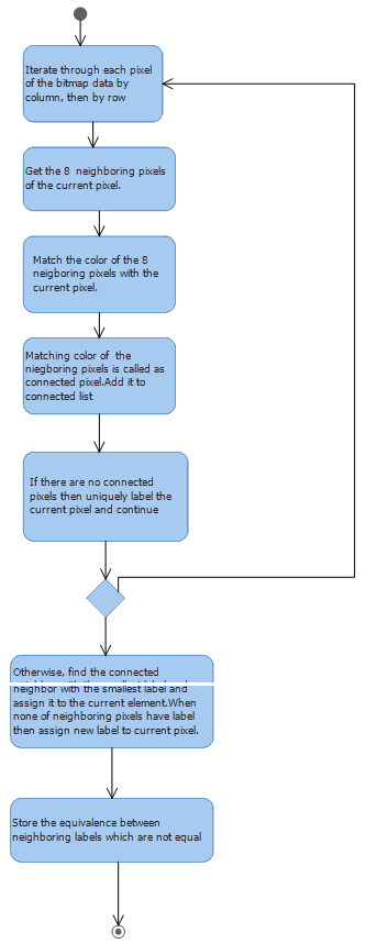
The below example illustrates how the image labeling algorithm perform as per the above flow chart.
以下示例说明了图像标记算法如何根据上述流程图执行。
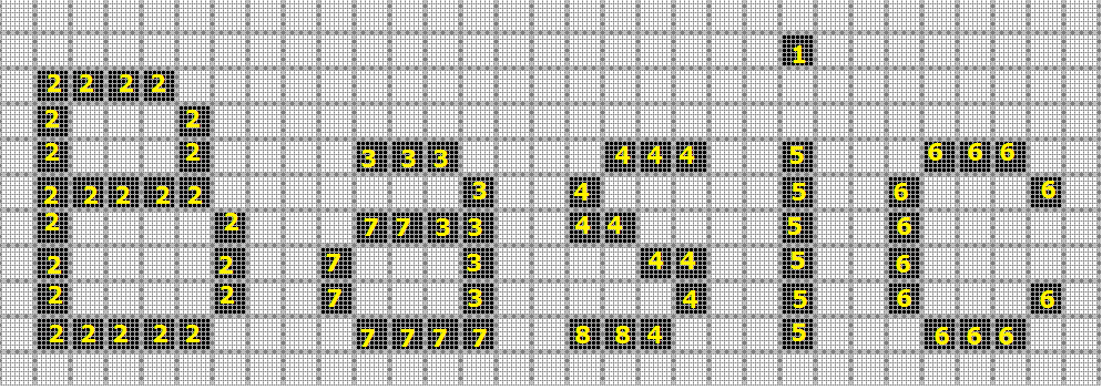
The label equivalence relationships generated are生成的标签等价关系是
| Set ID | Equivalent Labels |
|---|---|
| 1 | 1 |
| 2 | 2 |
| 3 | 3,7 |
| 4 | 4,8 |
| 5 | 5 |
| 6 | 6 |
| 7 | 3,7 |
| 8 | 4,8 |
注:为什么这么分组?是根据连通性检查,看有没有连接起来的情况。比如2组对应的像素点按8连接检查算法,都是连接在一起的。
On the second pass:在第二遍
The UML diagram below shows how the connected pixel, whose labels are not same, is assigned the lowest label value from the Equivalence record. In the end all the connected component will have the same label. Character "B" will have one label i.e. 2 and character "a" will have label 3.Once we get the relabel the distinct labels with
the available lowest label value from the equivalence record we get one complete connected component. Each character "B",
"a" etc will have distinct connect component. The character "i" has extra dot above so the Second pass algorithm also looks for extra dot above and
below connected component. So extra dot of "i" is also will be joined with label 5.下面的UML图显示了如何为其标签不相同的连接像素分配等效记录中的最低标签值。最后,所有连接的组件将具有相同的标签。字符“B”将具有一个标签,即2,
字符“a”将具有标签3.一旦我们得到重新标记具有来自等价记录的可用最低标签值的不同标签,我们得到一个完整的连接组件。每个字符“B”,“a”等将具有不同的连接组件。
字符“i”上方有额外的点,因此第二遍算法也在连接组件的上方和下方寻找额外的点。因此,“i”的额外点也将与标签5连接。
Finding boundary and Generating X, Y coordinate pixel array:寻找边界并生成X,Y坐标像素阵列:
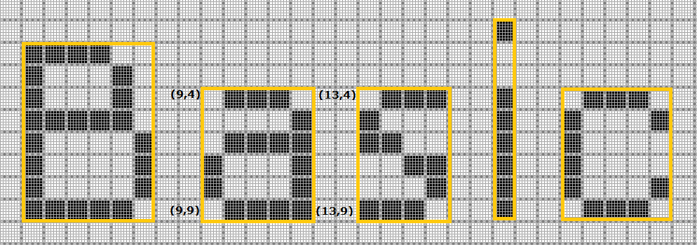
From the labels from the above algorithm, then its merely adding all the connected X, Y coordinates in the connect component list. The above image shows all the connected component boundary which marked in yellow. I have highlighted the boundary (X, Y) coordinates of the connected component "a".
从上面算法的标签,然后它只是在连接组件列表中添加所有连接的X,Y坐标。上图显示了以黄色标记的所有连接组件边界。我突出显示了连接组件“a”的边界(X,Y)坐标。
Explaining data in xml.
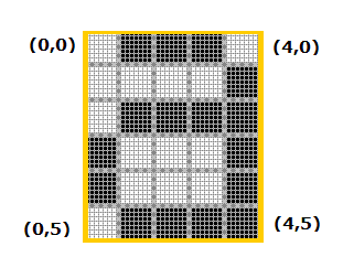
<characterinfo>
<ParamValue>a>⁄ParamValue>
<PixelInfo>
(0,3)(0,4)(1,0)(1,2)(1,5)(2,0)(2,2)(2,5)(3,0)(3,2)(3,5)(4,1)(4,2)(4,3)(4,4)(4,5)
<⁄PixelInfo>
<⁄characterinfo>
Let take the above bitmap image and pixel information in xml for character "a". As we see the boundary in yellow line. In above diagram the first pixel
coordinate (0,0) where X and Y coordinates are zero. As explained earlier the boundary conditions. The properties and their values are listed below.
让上面的位图图像和xml中的像素信息用于字符“a”。我们看到黄线的边界。在上图中,第一像素坐标(0,0),其中X和Y坐标为零。如前所述,边界条件。下面列出了属性及其值。
Note the connected X, Y coordinate in the xml.For "a" (0,3)(0,4) etc pixels are high so they are noted down.X,Y coordinates whose pixels are not high they are not noted.The tag <pixelinfo> represent the pixel coordinates whose pixels are high. The <ParamValue> tag has the character value "a".注意xml中连接的X,Y坐标。
对于“a”(0,3)(0,4)等像素是高的,所以它们被记下来.X,Y坐标,其像素不高,它们没有被注意到。
tag <pixelinfo>表示像素高的像素坐标。<ParamValue>标记具有字符值“a”。
Matching character:
Finally this most easy task. We match the connect component bit array with the xml data. Each pixel are matched according the X, Y coordinates. The fully matched pixels coordinates is the matched character from the xml.
Forming words.:
As per the above example "Basic". We maintain the LeftXindex and RightXindex for each character. The LeftXindex represent the left most index of the character in
the bitmap specified initially in the blog. The RightXindex represent the right most X coordinate of the character. When the difference coordinates of current
character and previous character is less than 3 pixels then they are joined. This algorithm is quite simple. But you can extend to join words according to
grammar in the dictionary.
I have attached the demo exe with the sample image. In the demo app just browse the image and click submit. The grid displays all the character with coordinates.
匹配角色:
最后这个最简单的任务。我们将连接组件位数组与xml数据进行匹配。每个像素根据X,Y坐标进行匹配。完全匹配的像素坐标是xml中匹配的字符。
形成单词:
按照上面的例子“Basic”。我们为每个角色维护LeftXindex和RightXindex。LeftXindex表示大数据中最初指定的位图中字符的最左侧索引。RightXindex表示角色的最右侧X坐标。
当前字符和前一个字符的差异坐标小于3个像素时,它们将被连接。这个算法很简单。但是你可以扩展到在字典中根据语法加入单词。
我已经使用示例图像附加了demo exe。在演示应用程序中,只需浏览图像并单击“提交”。网格显示带坐标的所有字符。