
精通
英语
和
开源
,
擅长
开发
与
培训
,
胸怀四海
第一信赖
精通
英语
和
开源
,
擅长
开发
与
培训
,
胸怀四海
第一信赖
锐英源精品开源心得,转载请注明:“锐英源www.wisestudy.cn,孙老师作品,电话13803810136。”需要全文内容也请联系孙老师。
This shop-floor equipment activity monitor application is part of a series of how-to Intel® Internet of Things (IoT) code sample exercises using the Intel® IoT Developer Kit, Intel® IoT Gateway, Intel® Edison board, cloud platforms, APIs, and other technologies.
From this exercise, developers will learn how to:
此车间设备活动监控应用程序是使用英特尔®物联网开发人员套件、英特尔®物联网网关、英特尔®Edison主板、云平台、API和其他技术进行的一系列英特尔®物联网(IoT)代码示例练习的一部分。
通过本练习,开发人员将学习如何:
Using an Intel® Edison board, this project lets you create a shop-floor equipment activity monitor that:
使用英特尔®Edison开发板,该项目可让您创建车间设备活动监视器:
This equipment activity monitor checks for sound and vibration.
If both parameters cross a predefined threshold, the display is lit to indicate the equipment is in use.
Once the equipment is no longer being used, the monitor clears the display.
Optionally, equipment usage start/stop events can be stored using the Intel® IoT Examples Data store or on an MQTT server running in your own Microsoft Azure*, IBM Bluemix*, or AWS* account.
此设备活动监视器检查声音和振动。
如果两个参数都超过预定义的阈值,则显示屏会亮起以指示设备正在使用中。
一旦设备不再使用,显示器将清除显示。
(可选)可以使用英特尔®物联网示例数据存储或在您自己的Microsoft Azure *,IBM Bluemix *或AWS *帐户中运行的MQTT服务器,存储设备使用开始/停止事件。
Grove* Starter Kit containing:
DFRobot* Starter Kit for Intel® Edison board, containing:
Grove *入门套件包含:
适用于英特尔®Edison开发板的DFRobot *入门套件,包含:
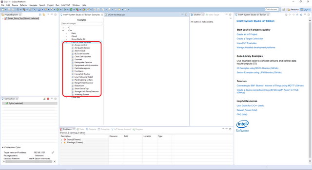
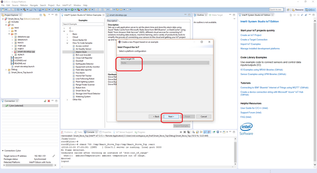
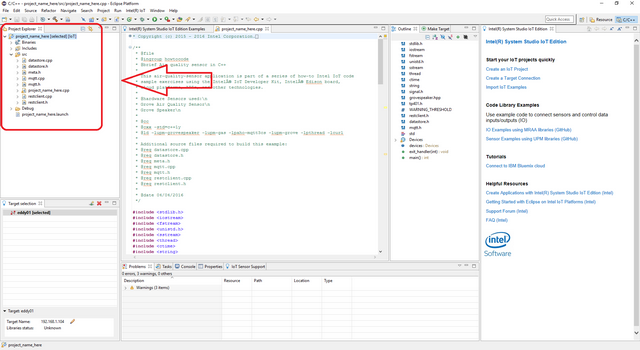
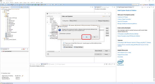
This sample is already one of the IoT examples included in Intel® System Studio. To start using it, follow these steps:
此示例已经是英特尔®SystemStudio中包含的IoT示例之一。要开始使用它,请按照下列步骤操作:
You need to have the Grove* Base Shield V2 connected to an Arduino* compatible breakout board to plug all the Grove devices into the Grove Base Shield V2. Make sure you have the tiny VCC switch on the Grove Base Shield V2 set to 5V.
您需要将Grove * Base Shield V2连接到Arduino *兼容分线板,将所有Grove设备插入Grove Base Shield V2。确保Grove Base Shield V2上的微型VCC开关设置为5V。
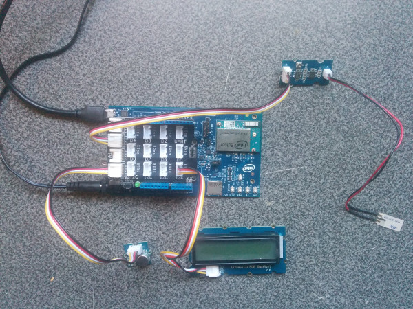
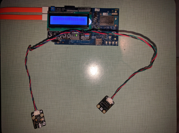
You need to have a LCD Keypad Shield connected to an Arduino* compatible breakout board to plug all the DFRobot* devices into the LCD Keypad Shield.
Plug one end of a DFRobot* cable into Analog Sound Sensor, then connect the other end to the A3 port on the LCD Keypad Shield.
Plug one end of a DFRobot* cable into the Digital Vibration Sensor, then connect the other end to the A2 port on the LCD Keypad Shield.
您需要将一个LCD键盘护罩连接到Arduino *兼容分线板,将所有DFRobot *设备插入LCD键盘护罩。
将DFRobot *电缆的一端插入模拟声音传感器,然后将另一端连接到LCD键盘护罩上的A3端口。
将DFRobot *电缆的一端插入数字振动传感器,然后将另一端连接到LCD键盘护罩上的A2端口。
This example uses the restclient-cpp library to perform REST calls to the remote data server. The code can be found in the lib directory. The restclient-cpp library requires the libcurl package, which is already installed on the Intel® Edison board by default.
此示例使用restclient-cpp库对远程数据服务器执行REST调用。代码可以在lib目录中找到。该RESTClient实现-CPP库需要的libcurl包,这已经是默认安装在英特尔®爱迪生板。
You can run this example using an Intel® IoT Gateway connected to an Arduino 101* (branded Genuino 101* outside the U.S.).
Make sure your Intel® IoT Gateway is setup using Intel® IoT Gateway Software Suite, by following the directions on the web site here:
https://software.intel.com/en-us/getting-started-with-intel-iot-gateways-and-iotdk
The Arduino 101* (branded Genuino 101* outside the U.S.) needs to have the Firmata* firmware installed. If you have IMRAA installed on your gateway, this will be done automatically. Otherwise, install the StandardFirmata or ConfigurableFirmata sketch manually onto your Arduino 101* (branded Genuino 101* outside the U.S.).
您可以使用连接到Arduino 101 *(美国以外的品牌Genuino 101 *)的英特尔®物联网网关来运行此示例。
请确保您的英特尔®物联网网关使用英特尔®物联网网关软件套件进行设置,请按照以下网站上的说明进行操作:
https://software.intel.com/en-us/getting-started-with-intel-iot-gateways-and-iotdk
Arduino 101 *(美国以外的品牌Genuino 101 *)需要安装Firmata *固件。如果您的网关上安装了IMRAA,则会自动完成。否则,请将StandardFirmata或ConfigurableFirmata草图手动安装到Arduino 101 *(美国以外的品牌Genuino 101 *)上。
Optionally, you can store the data generated by this sample program in a back-end database deployed using Microsoft Azure*, IBM Bluemix*, or AWS*, along with Node.js*, and a Redis* data store.
For information on how to set up your own cloud data server, go to:
https://github.com/intel-iot-devkit/intel-iot-examples-datastore
(可选)您可以将此示例程序生成的数据存储在使用Microsoft Azure *,IBM Bluemix *或AWS *部署的后端数据库中,以及Node.js *和Redis *数据存储中。
有关如何设置自己的云数据服务器的信息,请访问:
https://github.com/intel-iot-devkit/intel-iot-examples-datastore
You can also optionally store the data generated by this sample program using MQTT, a Machine To Machine messaging server. You can use MQTT to connect to Microsoft Azure*, IBM Bluemix*, or AWS*.
For information on how to connect to your own cloud MQTT messaging server, go to:
https://github.com/intel-iot-devkit/intel-iot-examples-mqtt
您还可以选择使用MQTT(机器到机器)消息服务器存储此示例程序生成的数据。您可以使用MQTT连接到Microsoft Azure *,IBM Bluemix *或AWS *。
有关如何连接到您自己的云MQTT消息服务器的信息,请转到:
https://github.com/intel-iot-devkit/intel-iot-examples-mqtt
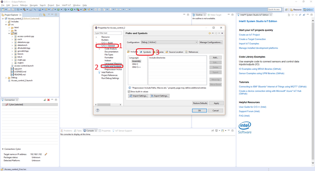
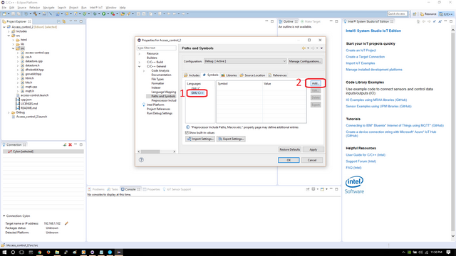
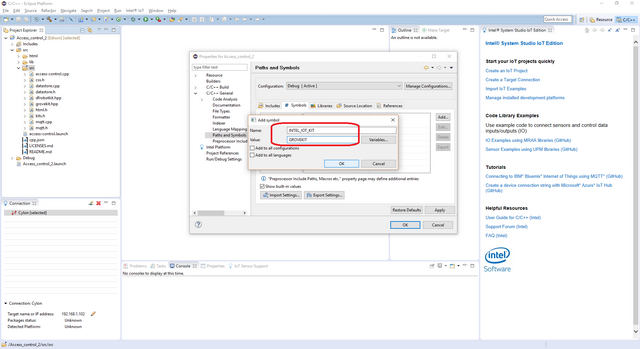
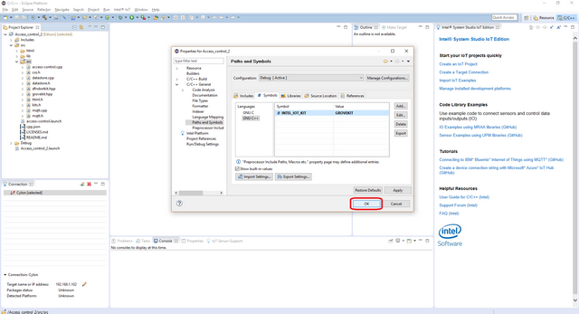
To configure the example for the specific hardware kit that you are using, either Grove* or DFRobot*:
要配置您正在使用的特定硬件套件的示例,请使用Grove *或DFRobot *:
If prompted for the username and password, the username is root and the password is whatever you specified when configuring the Intel® Edison board.如果提示输入用户名和密码,则用户名为root,密码为配置英特尔®Edison开发板时指定的密码。
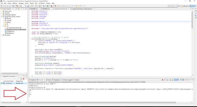
To run the example with the optional backend data store, you need to set the SERVER and AUTH_TOKENenvironment variables. You can do this in Eclipse as follows:
From the Run menu, select Run Configurations.
The Run Configurations dialog box is displayed.
Under C/C++ Remote Application, click doorbell.
This displays the information for the application.
In the Commands to execute before application field, add the following environment variables, except use the server and authentication token that correspond to your own setup:
要使用可选的后端数据存储运行示例,您需要设置SERVER和AUTH_TOKEN环境变量。您可以在Eclipse中执行以下操作:
从“ 运行”菜单中,选择“运行配置”。
系统弹出“运行配置”对话框。
在C / C ++远程应用程序下,单击门铃。
这将显示应用程序的信息。
在“ 在应用程序之前执行的命令”字段中,添加以下环境变量,但使用与您自己的设置对应的服务器和身份验证令牌:
chmod 755 /tmp/equipment-activity;
export SERVER="http://intel-examples.azurewebsites.net/logger/equipment-activity";
export AUTH_TOKEN="YOURTOKEN"
Click Apply to save your new environment variables.
Now when you run your program using the Run button, it should be able to call your server to save the data right from the Intel® Edison board Intel® IoT Gateway.
单击“ 应用”以保存新的环境变量。
现在,当您使用“ 运行”按钮运行程序时,它应该能够调用您的服务器以直接从英特尔®Edison开发板英特尔®物联网网关保存数据。
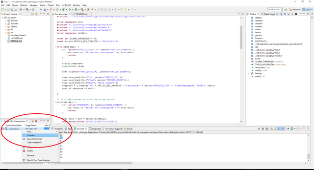
When you're ready to run the example, click Run at the top menu bar in Intel® System Studio.
准备好运行示例时,单击英特尔®SystemStudio顶部菜单栏中的“运行”。
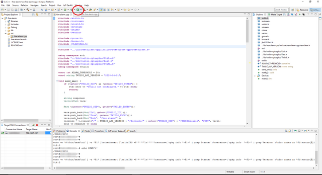
This compiles the program using the Cross G++ Compiler, links it using the Cross G++ Linker, transfers the binary to the Intel® Edison board Intel® IoT Gateway, and then executes it on the board itself.
After running the program, you should see output similar to the one in the image below.
这使用Cross G ++编译器编译程序,使用Cross G ++ Linker链接它,将二进制文件传输到英特尔®Edison主板英特尔®物联网网关,然后在主板上执行。
运行程序后,您应该看到类似于下图中的输出。

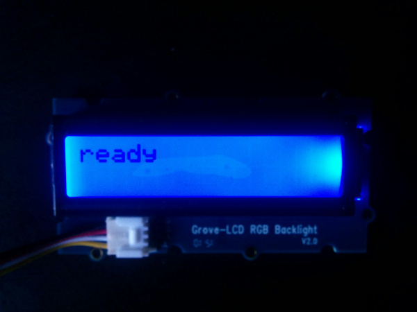
Successful output should be similar to the one in the image below.成功输出应类似于下图中的输出。
The LCD should now display ready.现在应该显示LCD ready。
IMPORTANT NOTICE: This software is sample software. It is not designed or intended for use in any medical, life-saving or life-sustaining systems, transportation systems, nuclear systems, or for any other mission-critical application in which the failure of the system could lead to critical injury or death. The software may not be fully tested and may contain bugs or errors; it may not be intended or suitable for commercial release. No regulatory approvals for the software have been obtained, and therefore software may not be certified for use in certain countries or environments.
重要提示:本软件为样本软件。它不是设计用于任何医疗,救生或生命维持系统,运输系统,核系统,也不是用于系统故障可能导致严重伤害或死亡的任何其他任务关键型应用。该软件可能未经过全面测试,可能包含错误或错误; 它可能无意或不适合商业发布。未获得该软件的监管批准,因此软件可能未经过认证,无法在某些国家/地区或环境中使用。